
Reducer, SDR 17 for Relining
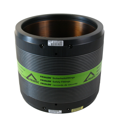
Reducer REM, SDR 17 for Relining
- Gas and water
- Working pressure: MOP (gas) 5 bar, PFA (water) 10 bar
- Material: PE 100
- Problem solver for pipe refurbishment work (relining)
- Safety technology
- Large insertion depth for good pipe routing (no holding devices required)
- Separate fusion zone
- Preheating technology
PE 100 SDR 17
Maximum permissible working pressure 10 bar (water) / 5 bar (gas)

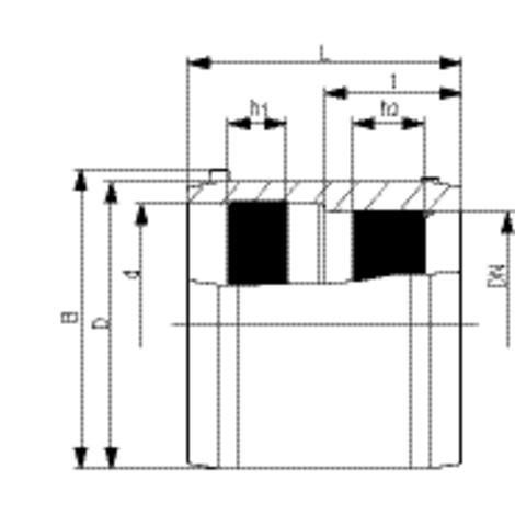
| Reference | Diameter | DN | SDR range | B | D | h1 | h2 | L | t | Weight [kg] | BX | Pallet quantity |
|---|---|---|---|---|---|---|---|---|---|---|---|---|
| 615571 | 160 | 150 | 17 - 26 | 199 | 190 | 38 | 42 | 180 | 90 | 1,550 | 12 | 96 |
| 615576 | 315 | 300 | 17 - 26 | 355 | 355 | 78 | 83 | 300 | 150 | 7,950 | 1 | 18 |
Areas of Application
The FRIALEN Relining Slide-over Coupler REM is used for connection from relining pipe to standard pipe.
Additional areas of application:
- Integration of adapters into an existing pipeline
- Connection of pipelines with fixed or restraint points
Assembly Instructions
The fusion of pipe ends with the FRIALEN Relining Slide-over Coupler REM takes place using FRIALEN-fusing - leakproof and longitudinally strong.
The pipe ends are prepared according to the general installation instructions (see assembly instructions for "FRIALEN-safety fittings"). This involves removing the oxide layer and cleaning the pipe ends. Please note that spigot of valves must be at least half as long as the coupler.
To compensate a larger annular gap (> 1 mm, max. 3 mm) between FRIALEN Relining Slide-over Coupler REM and pipe, the pre-heating barcode can be used for coupler REM d/DN 315/300 (see instruction leaflet packed up with the coupler).
For removal of the oxide layer, FWSG scraper tools are available which facilitate an uniform swarf removal and reproducible quality of the fusion area preparation.
Good reasons for using the FRIALEN-Relining Slide-over Coupler REM:
- Large coupler depth for ease of pipe guiding (no holding clamps required)
- Extra wide fusion zones
- Maximum stability through great wall thickness
- Cold zones at the front side and in the middle of the coupler
- Exposed heating coil for direct heat transmission to the pipe
- Small annular gap for build-up of optimum joining pressure in the fusion zone
- Touch proof electric contacts
- Fusion indicators for visual fusion control
- d/DN 315/300: pre-heating technique for a optimal gap-bridging
- d/DN 315/300: External reinforcement for an ideal fusion pressure
- Durable batch marking
- Individually wrapped for dirt protection
- Additional barcode for tracing back the fitting (Traceability-Coding)


 get_app
 get_app
